Microwave transmission refers to a technology for
transmitting information or energy through the use of radio waves, whose
wavelengths conveniently measured in a small number of centimeters, these are
called microwaves. This part of the radio spectrum ranges of frequencies of
about 1.0 gigahertz (GHz) to 30 GHz. These wavelengths correspond to 30 cm to
1.0 cm.
 Microwaves transmission are often used for point-to-point
communication, because their small wavelength enables convenient antennas in
narrow beams, which can direct be pointed directly at the receiving antenna.
This allows near microwave devices to the same frequencies used without
interfering with each other, since lower frequency radio waves to do. Another
advantage is that the high frequency of the microwaves from the microwave is a
very large volume data-carrying capacity, the microwave band has a bandwidth 30
times that of the rest of the spectrum below it. A disadvantage is that
microwaves are limited to line of sight propagation, they cannot pass around
hills and mountains than lower frequency radio waves can.
Microwaves transmission are often used for point-to-point
communication, because their small wavelength enables convenient antennas in
narrow beams, which can direct be pointed directly at the receiving antenna.
This allows near microwave devices to the same frequencies used without
interfering with each other, since lower frequency radio waves to do. Another
advantage is that the high frequency of the microwaves from the microwave is a
very large volume data-carrying capacity, the microwave band has a bandwidth 30
times that of the rest of the spectrum below it. A disadvantage is that
microwaves are limited to line of sight propagation, they cannot pass around
hills and mountains than lower frequency radio waves can.
Microwave radio transmission is typically using in
point-to-point communication systems on the surface of the earth, in satellite
communications, and in the depths of space, radio and television reception.
Other parts of the radio band are use for radar, radio navigation systems,
sensors, and radio astronomy.
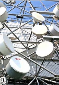
In order to use microwaves in narrow beams for
point-to-point communication links or radio location (radar), a satellite dish
is usually direct. This antenna uses a parabolic reflector to direct the
microwaves. To achieve narrow opening angle, the reflector must be much larger
than the wavelength of radio waves. The relatively short wavelength of
microwaves allows reasonably sized dishes that show the desired high
directivity for both the reception and transmission.
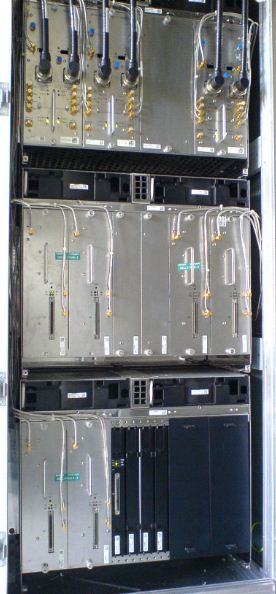
Microwave is a technology for transmitting digital and
analog signals, such as long distance cellular systems, television programs and
computer data between two points on a line of sight radio link. In microwave
radio links are between the two locations with directional antennas, with a
fixed radio link between the two points. The requirement of a line of sight
limits the distance between the stations 30 or 40 miles.

Since radio waves confined in narrow beams to a
line-of-sight path from one antenna to the other to travel, they do not
interfere with other microwave devices, microwave links and close to use the
same frequencies. Antennas are used, high directivity (high gain), these
antennas in places as large radio towers, installed to be able to transmit over
long distances. Typical types of antenna radio systems are used, parabolic
antennas, dielectric lenses and horn-reflector antennas, which have a diameter
of up to 4 meters. Very directional antennas provide an economical use of
available frequency spectrum, in spite of long transmission lines.
A microwave link is a communication system including a beam
of radio waves in the microwave frequency range to provide video, audio or data
between two locations, which can be apart from a few meters or feet to several
miles or kilometers to be transferred. Microwave links are often use by TV
stations to program in a country, for example, or from an outside broadcast van
to transfer back into the studio.
Characteristics of Radio Links
·
Obtain Line Of Sight (LOS) communication technology
·
Strongly Affected by the environment, including rain fade
·
Have very limited penetration capabilities
through obstacles such as mountains, buildings and trees
·
Sensitive to high pollen count
·
Signals can be degraded Events during the solar
proton
Uses of Radio Links
·
In communications between satellites and base
stations
·
As the backbone carrier for cellular systems
·
In short-range indoor communications
·
Telecommunications, the combination of remote
and regional exchanges for a larger super-exchange, without the need for
copper / fiber optic cables.


 Link Budget is the calculation of all gains and lossess from the transmitter through the medium (free space, cable, waveguide etc.) to a receiver in microwave telecommunication for line of sight radio system. It calculates the attenuation of transmitted signal due to propagation, antenna gains and other loses. Randomly, varying gains channel such as fading are taken into calculation by adding some margin depending on the anticipated severity effects. The margin required can be reduce by using mitigation techniques such as antenna diversity.